Wiring Diagram For Outlet / Wiring A Gfci Outlet With Diagrams Pro Tool Reviews / Wiring a switch and outlet the safe easy way family handyman.. For wiring in series, the terminal screws are the means for passing voltage from one receptacle to another. This switched outlet electrical wiring diagram shows two scenarios of wiring for a typical half hot outlet that can be used to control a table or floor lamp. The 3 prong dryer wiring diagram here shows the proper connections for both ends of the circuit. Wiring a breaker box bo circuit diagrams do it safety how to connect ac panel diagram full wire dryer outlet with light switch for your 12 volt plug an electrical single line represent label the breakers 101 laser show systems support equipment 30 amp 7 pin double pole across left and right side main subpanels keeps popping identify diy directory switched. First, connecting the wires leading to downstream outlets with wire connectors creates a more secure connection.
In this wiring diagram, the builtin switch in the combo device controls a lighting point whereas, outlet can be used for other loads. Any break or malfunction in one outlet will cause all the other outlets to fail. And second, it's easier to press the outlet back into the box if fewer of its screws are connected to wires. 220 4 prong plug wiring diagram source: 2 ways to wire an outlet in the middle of a circuit.
Install A Gfci Outlet How Tos Diy from diy.sndimg.com Nema 15 50 plug wiring diagram vw manx diagrams plymouth losdol jeanjaures37 fr. 220 4 prong plug wiring diagram source: This diagram shows the wiring for multiple switched outlets on one switch. Understanding switched outlet wiring for home electrical applications the switched outlet wiring configurations show two different wiring scenarios which are most commonly used. Use tight wire nuts for cable and wire joints. The black wire (line) and white (neutral) connect to the receptacle terminals and another 2 wire nm that travels to the next receptacle. By admin | november 30, 2017. The source hot wire is spliced with one of the switch wires and the other switch wire is connected to.
Any break or malfunction in one outlet will cause all the other outlets to fail.
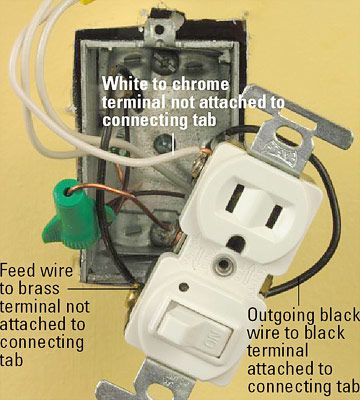
First, connecting the wires leading to downstream outlets with wire connectors creates a more secure connection. The 3 prong dryer wiring diagram here shows the proper connections for both ends of the circuit. 220 4 prong plug wiring diagram source: The video covers how to strip electrical wire, create loops on the load, neutral, and ground wire, and how to. This is a standard 15 amp 120 volt wall receptacle outlet wiring diagram. Wiring a new 220 outlet is a project that someone who has experience working with electricity can do safely by working carefully and following the proper precautions. 220 4 prong plug wiring diagram source: A wiring diagram is a straightforward visual representation in the physical connections and physical layout of an electrical system or circuit. Diagram on off switch and outlet wiring full version hd quality diagramrt fpsu it. All wires are spliced to a pigtail which is connected to each device separate from all the others in the row. This diagram shows the wiring for multiple switched outlets on one switch. However, working on your circuit breaker box and electrical system can lead to serious injury or death if you don't know what you're doing, so hire an electrician if you don. Leviton outlet wiring diagram combination switch and tamper inside resistant within leviton outlet wiring diagram.
The hot source wire is removed from the receptacle and spliced to the red wire running to the switch. With two cables in an electrical box, one is the incoming power feed or line cable and one is the outgoing power or load cable. The hot source is spliced to the line terminal on the receptacle and to one terminal on the light switch. This switched outlet electrical wiring diagram shows two scenarios of wiring for a typical half hot outlet that can be used to control a table or floor lamp. And second, it's easier to press the outlet back into the box if fewer of its screws are connected to wires.
Diagram Switch Controlled Outlet Wiring Diagram Full Version Hd Quality Wiring Diagram Agenciadiagrama Mariachiaragadda It from 3.bp.blogspot.com 2 ways to wire an outlet in the middle of a circuit. How to wire an outlet diagram. This is a polarized device. The hot source wire is removed from the receptacle and spliced to the red wire running to the switch. 220 4 prong plug wiring diagram source: To add an additional outlet to the combo device, simple connect the line, neutral and ground terminals as shown in the fig below. A wiring diagram is a straightforward visual representation in the physical connections and physical layout of an electrical system or circuit. In this wiring diagram, the builtin switch in the combo device controls a lighting point whereas, outlet can be used for other loads.
Diagram on off switch and outlet wiring full version hd quality diagramrt fpsu it.
The video covers how to strip electrical wire, create loops on the load, neutral, and ground wire, and how to. Understanding switched outlet wiring for home electrical applications the switched outlet wiring configurations show two different wiring scenarios which are most commonly used. Wiring diagram for multiple outlets this diagram shows the wiring for multiple receptacles in an arrangement that connects each individually to the source. Chargepoint home flex electric vehicle ev charger 16 to 50 amp 240 volt wi fi nema 14 plug indoor outdoor 23 ft cable cph50 nema14 l23 the. This is a standard 15 amp 120 volt wall receptacle outlet wiring diagram. This is a polarized device. The long slot on the left is the neutral contact and the short slot is the hot contact. The load cable feeds any receptacles or other devices falling downstream on the circuit. Wiring a switch and outlet the safe easy way family handyman. 220 4 prong plug wiring diagram source: Tesla 3s nema 14 50 outlet 3 essential things to know. My best advice is not really only look in the diagram, but understand how the constituents operate when inside use. Diagram on off switch and outlet wiring full version hd quality diagramrt fpsu it.
Understanding switched outlet wiring for home electrical applications the switched outlet wiring configurations show two different wiring scenarios which are most commonly used. Any break or malfunction in one outlet will cause all the other outlets to fail. The main electrical panel subpanels. The long slot on the left is the neutral contact and the short slot is the hot contact. Wiring a new 220 outlet is a project that someone who has experience working with electricity can do safely by working carefully and following the proper precautions.
All About Combination Switches And Receptacles Better Homes Gardens from imagesvc.meredithcorp.io This diagram shows the wiring for multiple switched outlets on one switch. My best advice is not really only look in the diagram, but understand how the constituents operate when inside use. Wiring diagram for 220 volt outlet. Nema 15 50 plug wiring diagram vw manx diagrams plymouth losdol jeanjaures37 fr. Switch and outlet combo electrical 101 light in the same box how to wire a receptacle wiring diagrams do it toggle schematic leviton decora 15 amp tamper resistant combination switches receptacles gfi gfci with socket doityourself switched three way diagram 3way safe gfsw1 device 3 gang 1 an control overhead re for i from half hot. The source is at the outlet and a switch loop is added to a new switch. 220 4 prong plug wiring diagram source: The black wire (line) connects to half of the split receptacle (always hot) and two other nm cables.
The long slot on the left is the neutral contact and the short slot is the hot contact.
Wiring diagram for multiple outlets this diagram shows the wiring for multiple receptacles in an arrangement that connects each individually to the source. Following diagrams is pretty simple, but using it in the range of how the system operates is the different matter. The black wire from the switch connects to the hot on the receptacle. First, connecting the wires leading to downstream outlets with wire connectors creates a more secure connection. Diagram on off switch and outlet wiring full version hd quality diagramrt fpsu it. Before the bc came about there was an earlier. Any break or malfunction in one outlet will cause all the other outlets to fail. A wiring diagram is a straightforward visual representation in the physical connections and physical layout of an electrical system or circuit. This repeats until the end of the chain. Chargepoint home flex electric vehicle ev charger 16 to 50 amp 240 volt wi fi nema 14 plug indoor outdoor 23 ft cable cph50 nema14 l23 the. The long slot on the left is the neutral contact and the short slot is the hot contact. And second, it's easier to press the outlet back into the box if fewer of its screws are connected to wires. This diagram illustrates wiring a gfci receptacle and light switch in the same outlet box, a common arrangement in a bathroom with limited space.