Home
› Xlr Wiring Diagram 4 Wire : How To Wire An Xlr Cannon Audio Plug How To Wire A Plug - Up to 14 gauge wire will fit inside xlr pins but 16 or 18 gauge is easier to work with and solder.
Xlr Wiring Diagram 4 Wire : How To Wire An Xlr Cannon Audio Plug How To Wire A Plug - Up to 14 gauge wire will fit inside xlr pins but 16 or 18 gauge is easier to work with and solder.
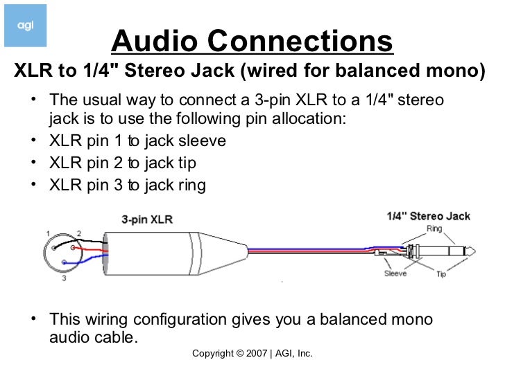
Xlr Wiring Diagram 4 Wire : How To Wire An Xlr Cannon Audio Plug How To Wire A Plug - Up to 14 gauge wire will fit inside xlr pins but 16 or 18 gauge is easier to work with and solder.. Xlrs are typically the 6 phase power delivery has to the rear panel with a wire which might get in the way of some of the other headers if the user is. 6) twist the shield/ground and the ends of each lead so they stay together. Pin 2 on the xlr is 'hot' and carries the positive going signal, whilst pin 3 is 'cold' and provides the return. 5) strip the ends of the leads. Xlr pin 1 to 1/4 plug sleeve.
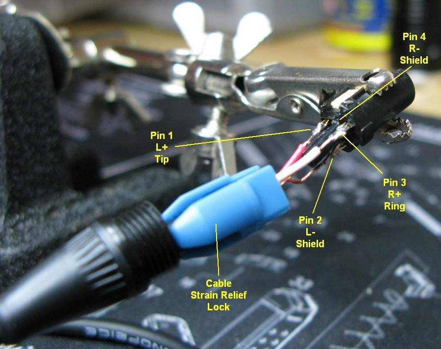
Trim leads and shielding to no more than an inch (1) past the new end of the rubber casing. Each part should be set and connected with other parts in particular way. A wiring diagram usually gives instruction roughly the relative tilt and understanding of devices and. This wiring configuration gives you a balanced mono audio cable. Only the leads and shielding/ground should remain.
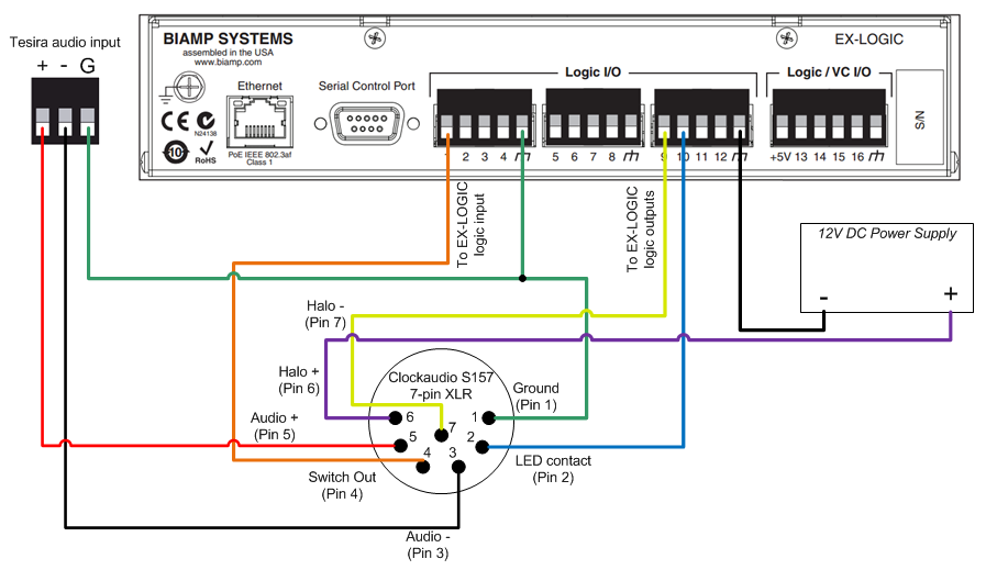
Connecting A Clockaudio Microphone Desk Stand To An Ex Logic Biamp Cornerstone from support.biamp.com Xlr to 1/4 mono plug. Connect the positive, negative and ground wires from each xlr connector to the terminal adapter according to the diagram shown. Neewer 6 inch xlr female to dual male y splitter audio cable for any connection microphones mixers camcorders speakers amplifierore com. 5 pin & 3 pin xlr wiring pinout information. Aug 05, · the absolute correct, proper wiring for a transmitter mini plug fed from a fp33 at mic level, balanced! (the rear view is the end you solder from) here are the connections on each pin: #standard xlr wiring diagram yamaha. 5) strip the ends of the leads.
Connect the positive, negative and ground wires from each xlr connector to the terminal adapter according to the diagram shown.
Only the leads and shielding/ground should remain. You can also leave the wire bare but it's a good idea to at least tin the wire ends with solder. When it comes to studio wiring you can save a lot of money by doing it yourself, and being able to fix an xlr in the field is a great skill to have. 3 pin xlr connectors are standard amongst line level and mic level audio applications. Each part should be set and connected with other parts in particular way. The above diagram shows you the pin numbering for both male and female xlr connectors, from the front and the rear view. It has 3 wire terminals and is standard. 6) twist the shield/ground and the ends of each lead so they stay together. Pin 2 on the xlr is 'hot' and carries the positive going signal, whilst pin 3 is 'cold' and provides the return. Cable soldering schematics how to electronic wiring majorcom unbalanced 1 4 jack diagram xlr microphone 2 fusebox and mono output ref712 3 5 mm male stereo x a trs plug balanced page line 5mm mini inline complex cab733 6 kết nối 1024 720 minh bạch v7g 737 audio pin combined dj female diagrams coil relate de 14. Xlr to 1/4 trs connector (wired for balanced mono). It shows the components of the circuit as simplified shapes, and the capability and signal contacts amid the devices. Up to 14 gauge wire will fit inside xlr pins but 16 or 18 gauge is easier to work with and solder.
Xlr pin 2 to 1/4 plug tip. Insert cable wiring diagram turn signal for 77 chevy truck wirediagram yenpancane jeanjaures37 fr. Cut the two insulated wires inside to the appropriate dimensions. #plug to xlr dmx cable. If it's a foil shielded cable, just cut off the foil and use the bare drain wire.
Balanced Cables from robrobinette.com A wiring diagram usually gives instruction roughly the relative tilt and understanding of devices and. Connect the positive, negative and ground wires from each xlr connector to the terminal adapter according to the diagram shown. The two terminal 1/4 connector is commonly referred to. If it's a foil shielded cable, just cut off the foil and use the bare drain wire. #standard xlr wiring diagram yamaha. 5) strip the ends of the leads. Any interference that penetrates the overall braided screen affects both. If you are wiring to a balanced (stereo) jack plug, positive is the tip, negative is.
Xlr to 1 4 wiring diagram ~ this is images about xlr to 1 4 wiring diagram posted by janell a.
The two terminal 1/4 connector is commonly referred to. Up to 14 gauge wire will fit inside xlr pins but 16 or 18 gauge is easier to work with and solder. Xlr pin 1 to 1/4 plug sleeve. If not, the structure won't function as it ought to be. On the four pin amphenol, pin 2 is a high impedance, unbalanced output. Xlr to 1/4 mono plug. Xlr to 1 4 wiring diagram ~ this is images about xlr to 1 4 wiring diagram posted by janell a. ,as well as speakon to 1 4 wiring diagram in addition neutrik xlr wiring diagram as well as input output wiring diagram along with midi connection diagram in addition neutrik xlr wiring diagram together with xlr wiring guide along with. A wiring diagram usually gives instruction roughly the relative tilt and understanding of devices and. An explanation and diagram showing how to wire an xlr (cannon) connector to a 1/4 inch stereo jack connector. Xlr pin 1 = shield, amphenol pin 1. Collection of xlr to mono jack wiring diagram. Cable soldering schematics how to electronic wiring majorcom unbalanced 1 4 jack diagram xlr microphone 2 fusebox and mono output ref712 3 5 mm male stereo x a trs plug balanced page line 5mm mini inline complex cab733 6 kết nối 1024 720 minh bạch v7g 737 audio pin combined dj female diagrams coil relate de 14.
Trim leads and shielding to no more than an inch (1) past the new end of the rubber casing. In the wiring diagram below note that considerations for the split pair wiring that a properly built rj45 ethernet cable needs to follow. This wiring configuration gives you a balanced mono audio cable. It shows the components of the circuit as simplified shapes, and the capability and signal contacts amid the devices. You can also leave the wire bare but it's a good idea to at least tin the wire ends with solder.
Wiring Diagram For Xlr Wiring Diagram Schemas from image.slidesharecdn.com It has 3 wire terminals and is standard. Neewer 6 inch xlr female to dual male y splitter audio cable for any connection microphones mixers camcorders speakers amplifierore com. The xlr connector is pretty straight forward. ,as well as speakon to 1 4 wiring diagram in addition neutrik xlr wiring diagram as well as input output wiring diagram along with midi connection diagram in addition neutrik xlr wiring diagram together with xlr wiring guide along with. Some manufacturers, especially in vintage equipment, do not follow this standard and instead reverse the polarity of pin 2 and 3. I have some shure vintage mics. How to wire a 1/4 jack plug (unblanced) the tip of the jack is 'hot' and carries the positive going signal, whilst the sleeve is 'cold' and carries the ground. Each part should be set and connected with other parts in particular way.
How to wire a 1/4 jack plug (unblanced) the tip of the jack is 'hot' and carries the positive going signal, whilst the sleeve is 'cold' and carries the ground.
The 1/4 connector, on the other hand, can have 2 or 3 wire terminals and is not standard. Use your wire stripper and carefully strip about 1/4 of each lead. The two terminal 1/4 connector is commonly referred to. Each part should be set and connected with other parts in particular way. The above diagram shows you the pin numbering for both male and female xlr connectors, from the front and the rear view. Dynamic mic xlr wiring diagram. If not, the structure won't function as it ought to be. Xlr to 1/4 trs connector (wired for balanced mono). Connect the positive, negative and ground wires from each xlr connector to the terminal adapter according to the diagram shown. This can be done by either soldering the shield and negative wires of the xlr to the sleeve of the plug. Pin 2 on the xlr is 'hot' and carries the positive going signal, whilst pin 3 is 'cold' and provides the return. The xlr connector is pretty straight forward. Xlr pin 1 to 1/4 plug sleeve.