Home
› Lighting Circuit Wiring : Uk Domestic Lighting Circuits Loop In At Ceiling Rose Loop In At Switch Youtube - Wiring is to be installed in metal raceways or as required by art.
Lighting Circuit Wiring : Uk Domestic Lighting Circuits Loop In At Ceiling Rose Loop In At Switch Youtube - Wiring is to be installed in metal raceways or as required by art.
Lighting Circuit Wiring : Uk Domestic Lighting Circuits Loop In At Ceiling Rose Loop In At Switch Youtube - Wiring is to be installed in metal raceways or as required by art.. Lighting circuits using junction boxes. 15 amp circuits are the most common. An alternative method, this uses the same wiring principles as the looped ceiling roses, but here the connections are made in junction boxes rather than the ceiling rose. How to wire a simple 120v electrical circuit. Parallel wiring allows the full power of the circuit to be delivered to each light fixture or device.
The permanent live wire is wired into the switch and the switched live into the switched live terminal. 15 amp circuits are the most common. The common household circuits used in electrical wiring installation are (and should be) in parallel. Sometimes it is handy to have an outlet controlled by a switch. Lighting circuits using junction boxes.
Resources from emedia.rmit.edu.au Step by step instructions on how to wire a switched outlet. 15 amps circuits allow for less expensive 14 gauge wire. The permanent live wire is wired into the switch and the switched live into the switched live terminal. Our example uses 14 gauge wire. Wiring is to be installed in metal raceways or as required by art. However, in this guide we'll focus on the lighting circuit wiring. The common household circuits used in electrical wiring installation are (and should be) in parallel. Disengage the wires by twisting the wiring cap until it comes free.
The requirements of a lighting application often dictate what type of circuit can be used, but if given the choice, the most efficient way to run high power leds is using a series circuit with a constant current led driver.
From the ceiling box an electrical receptacle outlet is fed power. The cable used is a 1sq mm pvc twin core and earth rated for up to 12 amps. Our example uses 14 gauge wire. Full set of wiring diagrams (new cable colours) When wiring in series the electrical power is routed through each light fixture or device which then creates resistance on the circuit. The consumer unit is normally connected to the first lamp, which in turn is connected to the second lamp and so on. 15 amps circuits allow for less expensive 14 gauge wire. This is usually a distribution board of some sort. You should see plastic caps, called wiring caps (also called a wire nut), with two wires running into each cap. However, in this guide we'll focus on the lighting circuit wiring. High supply voltage are needed if we need to add more load (light bulbs, electric heaters, air conditioner etc) in the series circuit. We have and extensive collection of common lighting arrangements with detailed lighting circuit diagrams, light wiring diagrams and a breakdown of all the components used in lighting circuits. A basic explanation of lighting wiring.
Running a series circuit helps to provide the same amount of current to each led. Hiring an electrician is usually the best way to go where 120 volt circuits are concerned, but if you are up to it, you might save money by doing some basic electrical work yourself. This wire is needed to complete the circuit. Instead of taking the feed wire from the consumer unit to the ceiling rose it is taken to the switch. 15 amp circuits are the most common.
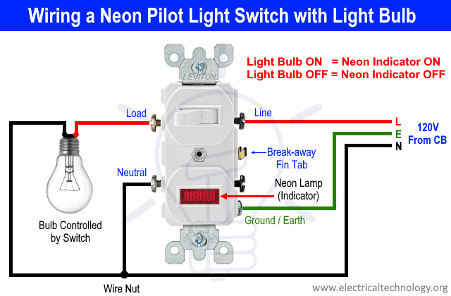
How To Wire A Pilot Light Switch 2 And 3 Way Wiring from www.electricaltechnology.org Instead of taking the feed wire from the consumer unit to the ceiling rose it is taken to the switch. From the ceiling box an electrical receptacle outlet is fed power. Running a series circuit helps to provide the same amount of current to each led. Every lighting system needs a cable from the mains to supply power to all the lighting points and a switch that can interrupt the supply to each individual point. The ground wire (sometimes in a green jacket) should be connected to your switch and to your lights. Wiring is to be installed in metal raceways or as required by art. Step by step instructions on how to wire a switched outlet. However, in this guide we'll focus on the lighting circuit wiring.
Parallel wiring allows the full power of the circuit to be delivered to each light fixture or device.
Mar 09, 21 09:56 pm. 15 amp circuits are the most common. As you can see, a basic lighting circuit consists only of three components: Parallel wiring allows the full power of the circuit to be delivered to each light fixture or device. Three way switching, 3 wires Series wiring is all or none type wiring mean all the appliances will work at once or all of them will disconnect if fault occurs at any one of the connected device in series circuit. Running a series circuit helps to provide the same amount of current to each led. How to wire a simple 120v electrical circuit. You should see plastic caps, called wiring caps (also called a wire nut), with two wires running into each cap. The consumer unit is normally connected to the first lamp, which in turn is connected to the second lamp and so on. Here we will explain how the most common lighting circuit works. This is an alternative way of wiring a lighting circuit. 15 amps circuits allow for less expensive 14 gauge wire.
An enthusiastic homeowner can save the cost of a professional by knowing which wires connect to which. Mostly, switches, outlet receptacles and light points etc are connected in parallel to maintain the power supply to other electrical devices and appliances through hot and neutral wire in case if one of them gets fail. The neutrals are connected together using a terminal connector. One wire will come from the light, the other from the main electrical circuit of your house. The white or neutral wire bypasses the switch and goes straight to your lights.
Diagram Single Bulb Ceiling Light Wiring Diagram Full Version Hd Quality Wiring Diagram Diagrampart Eterotopie It from www.ultimatehandyman.co.uk The cable used is a 1sq mm pvc twin core and earth rated for up to 12 amps. An enthusiastic homeowner can save the cost of a professional by knowing which wires connect to which. The common household circuits used in electrical wiring installation are (and should be) in parallel. Hiring an electrician is usually the best way to go where 120 volt circuits are concerned, but if you are up to it, you might save money by doing some basic electrical work yourself. Three way switching, 3 wires The diagram above shows a two conductor cable from the circuit breaker panel going to a wall switch. One wire will come from the light, the other from the main electrical circuit of your house. Most light fixtures have two electrical wires with colored insulation and a copper ground wire.
If you have longer lengths to cover, 1.5mm squared cable can be used and the maximum length allowed using this is 110m.
From the ceiling box an electrical receptacle outlet is fed power. Parallel wiring allows the full power of the circuit to be delivered to each light fixture or device. We have and extensive collection of common lighting arrangements with detailed lighting circuit diagrams, light wiring diagrams and a breakdown of all the components used in lighting circuits. The junction box effectively replaces the ceiling rose. The reason why the wiring of a lighting circuit is more complex than a power circuit is that each outlet or light fitting needs to be controlled by a separate switch. Sometimes it is handy to have an outlet controlled by a switch. I concentrated on particular one where all cables are connected at the switch. Using 1mm cable is allowed for up to 95meters of circuit length. When the electrical source originates at a light fixture and is controlled from a remote location, a switch loop is used. The neutrals are connected together using a terminal connector. You should see plastic caps, called wiring caps (also called a wire nut), with two wires running into each cap. Draw a sketch of your room that shows lighting, switch and outlet locations. This wire is needed to complete the circuit.