Diy Arduino Board Circuit Diagram / 3dpBurner: Basic wiring diagram | Arduino projeleri, Arduino, Ahşap işleme / Diy arduino uno v1.0 schematic design pcb layout.. Shown below is one of my diy arduino circuits. To make the schematic, use the arduino nano circuit diagram and arduino nano components list. So whenever i turn the arduino the first relay is on and its on for 3 seconds and after that it goes off and the second relay is on 3 sec similarly for third and fourth and after fourth all will be off for 3 seconds and after that all four legs will be turned on. A reset switch is placed left upper corner of arduino board for restarting the program within the arduino itself. If you don't have an easy way to order an arduino board or kit, you can etch this pcb design by hand and solder it together.
Diagram motor wiring diagram for rc quadcopter full version hd quality rc quadcopter bizwiring italiadogshow it Atmega328 ic is the brain of the arduino board. The colpitts oscillator, on the bottom left on the diagram, feeds the oscillation into counter 1 (pin t1) of the chip (marked as digital pin 5 on the arduino uno), where it constantly counts the frequency of oscillation. If you are just getting started with arduino, you don't have to worry about that. Rf transmitter and receiver circuit diagram.
DIY Motorized Camera Slider with Pan and Tilt Head - Arduino Based Project | Diy camera slider ... from i.pinimg.com Atmega328 ic is the brain of the arduino board. Welcome to my vast collection of arduino projects. As i have mentioned earlier, the first and important part to make your own arduino board is to have a clear idea on the design of the board. Here the arduino uno schematic diagram (click to enlarge): I then removed the atmega328 from the development board and embedded into a perfboard along with the rest of the circuit. Altitude, roll, yaw, and pitch. The icsp connection (6 pins comming out the side) on this circuit is perfectly connected to the sparkfun ftdi breakout board: Here is the best way to make a perfect diy arduino ,making the custom arduino board is simple and perfect way.
For measuring voltages less than or equal to 5v, the first circuit can be used.
I then removed the atmega328 from the development board and embedded into a perfboard along with the rest of the circuit. You don't need a bunch of hookup wire, the general purpose pcb is looking ugly with a bunch of hookup wires. Each of the following diy arduino projects is covered with detailed step by step tutorial on how to do it yourself and includes circuit schematics, source codes and videos. Altitude, roll, yaw, and pitch. This step starts with building the circuit. Diy arduino uno v1.0 schematic design pcb layout. Similar steps are followed for the pcb layout as it is followed for schematic capture. Click upload button to send sketch to the arduino. Eagle cad was used initially and later the file is imported into kicad. Typically the arduino board is used for these adjustments autonomously. This is the third revision of the board: Heres an example of a circuit using the arduino duemilanove and a 7 segment red led 03 digital display radioshack 276 075. Shown below is one of my diy arduino circuits.
If you are just getting started with arduino, you don't have to worry about that. Very often i need wireless control for the projects that i make, so therefore i built this multifunctional radio controller which can be used for pretty much everything. As i have mentioned earlier, the first and important part to make your own arduino board is to have a clear idea on the design of the board. Select the board and serial port as outlined in earlier section. The arduino can create a file in an sd card to write and save data using the sd library.
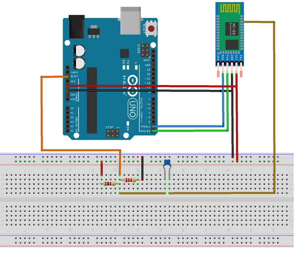
DIY Arduino Wireless Programming Shield using Bluetooth Module from circuitdigest.com The arduino can create a file in an sd card to write and save data using the sd library. But if a custom pcb you don't need much hookup wire and less chance to short circuits. Microcontroller section of diy arduino uno v1.0; A usb 2.0 type b placed right corner of arduino (depending on how you place) for powering and burn programs to microcontroller. Each of the following diy arduino projects is covered with detailed step by step tutorial on how to do it yourself and includes circuit schematics, source codes and videos. Altitude, roll, yaw, and pitch. I just programmed the arduino and attach with my homemade relay circuit board and connect all four appliances with the relay board. A reset switch is placed left upper corner of arduino board for restarting the program within the arduino itself.
Eagle cad was used initially and later the file is imported into kicad.
Diagram of a rc drone easy wiring diagrams rf based wireless remote control switch syma x8hg x8hw x8hc remote control receiver circuit board rc. You will also need two arduino boards for this: Eagle cad was used initially and later the file is imported into kicad. Altitude, roll, yaw, and pitch. The circuit does not have the ftdi chip built in. But if a custom pcb you don't need much hookup wire and less chance to short circuits. If you don't have an easy way to order an arduino board or kit, you can etch this pcb design by hand and solder it together. You don't need a bunch of hookup wire, the general purpose pcb is looking ugly with a bunch of hookup wires. Heres an example of a circuit using the arduino duemilanove and a 7 segment red led 03 digital display radioshack 276 075. A reset switch is placed left upper corner of arduino board for restarting the program within the arduino itself. The arduino can create a file in an sd card to write and save data using the sd library. Arduino high voltage driver circuit using irf9540 power mosfet syed saad hasan february 25, 2020 when using an arduino, we often need to control more voltage/current that than can be handled directly from. Connect the arduino board to your computer using the usb cable.
The arduino can create a file in an sd card to write and save data using the sd library. This is the third revision of the board: However, it does not have ft232rl chip, therefore, you would need a separate ftdi basic module to burn your sketch. Select the board and serial port as outlined in earlier section. The colpitts oscillator, on the bottom left on the diagram, feeds the oscillation into counter 1 (pin t1) of the chip (marked as digital pin 5 on the arduino uno), where it constantly counts the frequency of oscillation.
A. Example of an electrocardiogram circuit wired to an Arduino... | Download Scientific Diagram from www.researchgate.net Click upload button to send sketch to the arduino. Typically the arduino board is used for these adjustments autonomously. The arduino sd card module is especially useful for projects & tutorial that require data logging. Diagram of a rc drone easy wiring diagrams rf based wireless remote control switch syma x8hg x8hw x8hc remote control receiver circuit board rc. Connect the arduino board to your computer using the usb cable. This step starts with building the circuit. As i have mentioned earlier, the first and important part to make your own arduino board is to have a clear idea on the design of the board. When creating an arduino circuit diagram all you need to do is simply drag and drop the devices from the toolbox onto the drawing area and arrange them appropriately around an arduino board and a breadboard.
Instead, we can use standalone atmega328 ic which can be programmed with arduino ide without using the arduino board.
This step starts with building the circuit. Very often i need wireless control for the projects that i make, so therefore i built this multifunctional radio controller which can be used for pretty much everything. To make the schematic, use the arduino nano circuit diagram and arduino nano components list. Click upload button to send sketch to the arduino. The arduino sd card module is especially useful for projects & tutorial that require data logging. Atmega328 ic is the brain of the arduino board. Eagle cad was used initially and later the file is imported into kicad. This project is identical to project #1 except that we will be building it on a breadboard. Here the arduino uno schematic diagram (click to enlarge): I just programmed the arduino and attach with my homemade relay circuit board and connect all four appliances with the relay board. Once it's drawn completely, open the pcb designing part of the software and you'll see that schematic is imported there. You will also need two arduino boards for this: A 3d view / render of the pcb is also available in kicad.