Home
› Half Adder Logic Diagram And Truth Table - C++ Programming For Beginners: Half Subtractor and Full Subtractor / Full subtractor in digital logic.
Half Adder Logic Diagram And Truth Table - C++ Programming For Beginners: Half Subtractor and Full Subtractor / Full subtractor in digital logic.
Half Adder Logic Diagram And Truth Table - C++ Programming For Beginners: Half Subtractor and Full Subtractor / Full subtractor in digital logic.. The full adder circuit diagram add three binary bits and gives result as sum, carry out. This circuit constructed using half adder circuitry it requires two xor gates, two and and one or. Its used to calculate sum of two 1 bit inputs using a circuit. A half adder is defined as a basic four terminal digital device which adds two binary input bits. A demultiplexer performs the reverse operation of a multiplexer i.e.
It outputs the sum binary bit and a carry binary bit. In these circuits there are n input variables obtained from an external source are of binary once the equations are obtained the logic diagram for the adder circuit is designed. First half adder circuit's sum output is further provided to the second half adder circuit's input. Half adder and half subtractor using nand nor gates. It receives one input and distributes it over several.
Digital Electronics - Digital Logic Short Study Notes » ExamRadar from examradar.com N a combinational circuit that performs the addition of two bits is called a half adder. Since any addition where a carry is present isn't complete without adding the carry, the operation is not complete. A and b, and the corresponding carry out co. Full subtractor in digital logic. Truth table and schematic representation. If any of the half adder logic produces a carry, there will be an output carry. Half adder using discrete logic gates. N logic circuits for digital systems may be combinational or sequential.
Nand gates or nor gates can be used for realizing the half adder in universal logic and the relevant circuit diagrams are shown in the figure below.
Half adder using discrete logic gates. Truth table of the half adder. Match those of the input d when the clock is enabled.the d. Circuit diagram of half adder using nand gates. In these circuits there are n input variables obtained from an external source are of binary once the equations are obtained the logic diagram for the adder circuit is designed. The circuit diagram for simulating the half adder above, the d. A half adder is used for adding together the two least significant digits in a binary sum such as the one shown in figure 12.1(a). An adder is a digital logic circuit in electronics that performs the operation of additions of two number. This circuit constructed using half adder circuitry it requires two xor gates, two and and one or. Half adder using nand gates. N logic circuits for digital systems may be combinational or sequential. Nand gate is a universal gate which means any kind of logic gate or function schematic diagrams of full adders. Full subtractor in digital logic.
A half adder is defined as a basic four terminal digital device which adds two binary input bits. One is half adder and another one is known as full adder. N logic circuits for digital systems may be combinational or sequential. Since any addition where a carry is present isn't complete without adding the carry, the operation is not complete. • two half adders can be used to add 3 bits.
C++ Programming For Beginners: Half Subtractor and Full Subtractor from 4.bp.blogspot.com If any of the half adder logic produces a carry, there will be an output carry. Learn what a half adder is, see the circuit behind it, and a truth table for a half adder. Half adder and half subtractor using nand nor gates. A version of this diagram showing the two half adder modules outlined is available here. The full adder (fa) circuit has three inputs: Its used to calculate sum of two 1 bit inputs using a circuit. Nand gate is a universal gate which means any kind of logic gate or function schematic diagrams of full adders. A simple explanation of a half adder.
Adders are classified into two types:
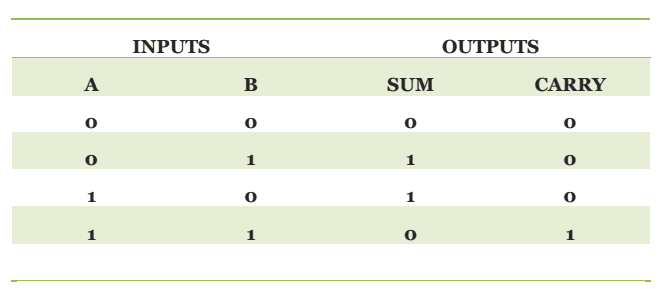
It outputs the sum binary bit and a carry binary bit. Learn what a half adder is, see the circuit behind it, and a truth table for a half adder. .with truth table full adder logic circuit we can implement a full adder circuit with the help of two half adder circuits. Half adder is a combinational logic circuit with two inputs and two outputs. Truth table of the half adder. It is used to find out if a propositional expression is true for all legitimate input values. It receives one input and distributes it over several. We provided the carry in bit across the other input of in the above image, instead of block diagram, actual symbols are shown. Match those of the input d when the clock is enabled.the d. A simple explanation of a half adder. N logic circuits for digital systems may be combinational or sequential. The circuit diagram for simulating the half adder above, the d. Title=half adder | truth table & logic diagram class.
Since any addition where a carry is present isn't complete without adding the carry, the operation is not complete. The truth table of half adder is given below. The full adder (fa) circuit has three inputs: According to this expression schematic for full adder's sum is. A demultiplexer performs the reverse operation of a multiplexer i.e.
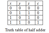
Solved: A half adder is a combinational logic circuit that has ... | Chegg.com from media.cheggcdn.com The truth table of half adder is given below. Although by itself, a half figure.1: Title=half adder | truth table & logic diagram class. If any of the half adder logic produces a carry, there will be an output carry. Half adder is a combinational logic circuit used for the purpose of adding two single bit numbers. 28.10.2020 · half adder truth table from the above truth table, we can see that the sum digit of two binary inputs is the outcome of xor operation and we can realize it by using an xor gate. N a combinational circuit that performs the addition of two bits is called a half adder. It is used to find out if a propositional expression is true for all legitimate input values.
A simple explanation of a half adder.
Half adder definition, block diagram, truth table, circuit diagram, logic diagram, boolean expression and equation are discussed. Half adder is a combinational logic circuit with two inputs and two outputs. We provided the carry in bit across the other input of in the above image, instead of block diagram, actual symbols are shown. A version of this diagram showing the two half adder modules outlined is available here. The truth table for this design is shown in table 5.26. A demultiplexer performs the reverse operation of a multiplexer i.e. The second half adder logic can be used to add cin to the sum produced by the first half adder circuit. Half adder using nand gates. Half adder and half subtractor using nand nor gates. Its used to calculate sum of two 1 bit inputs using a circuit. An adder is a digital logic circuit in electronics that performs the operation of additions of two number. The truth table is shown. According to this expression schematic for full adder's sum is.